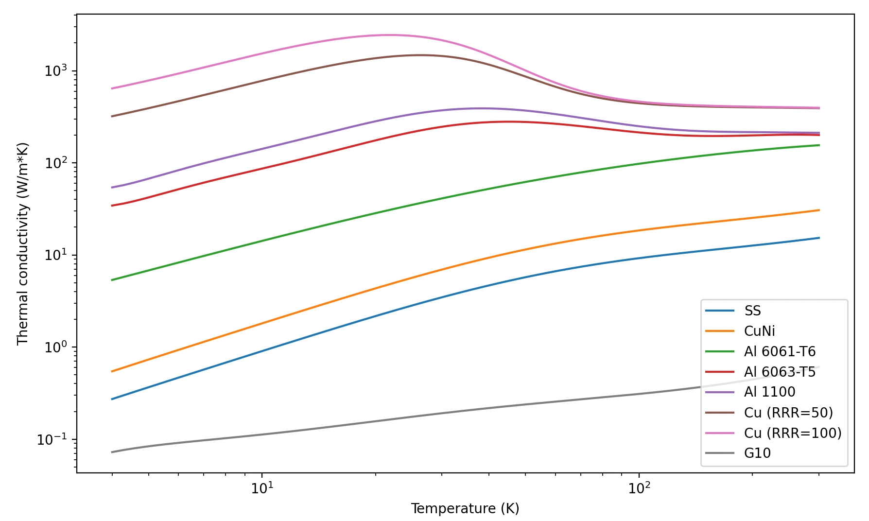
Material selection
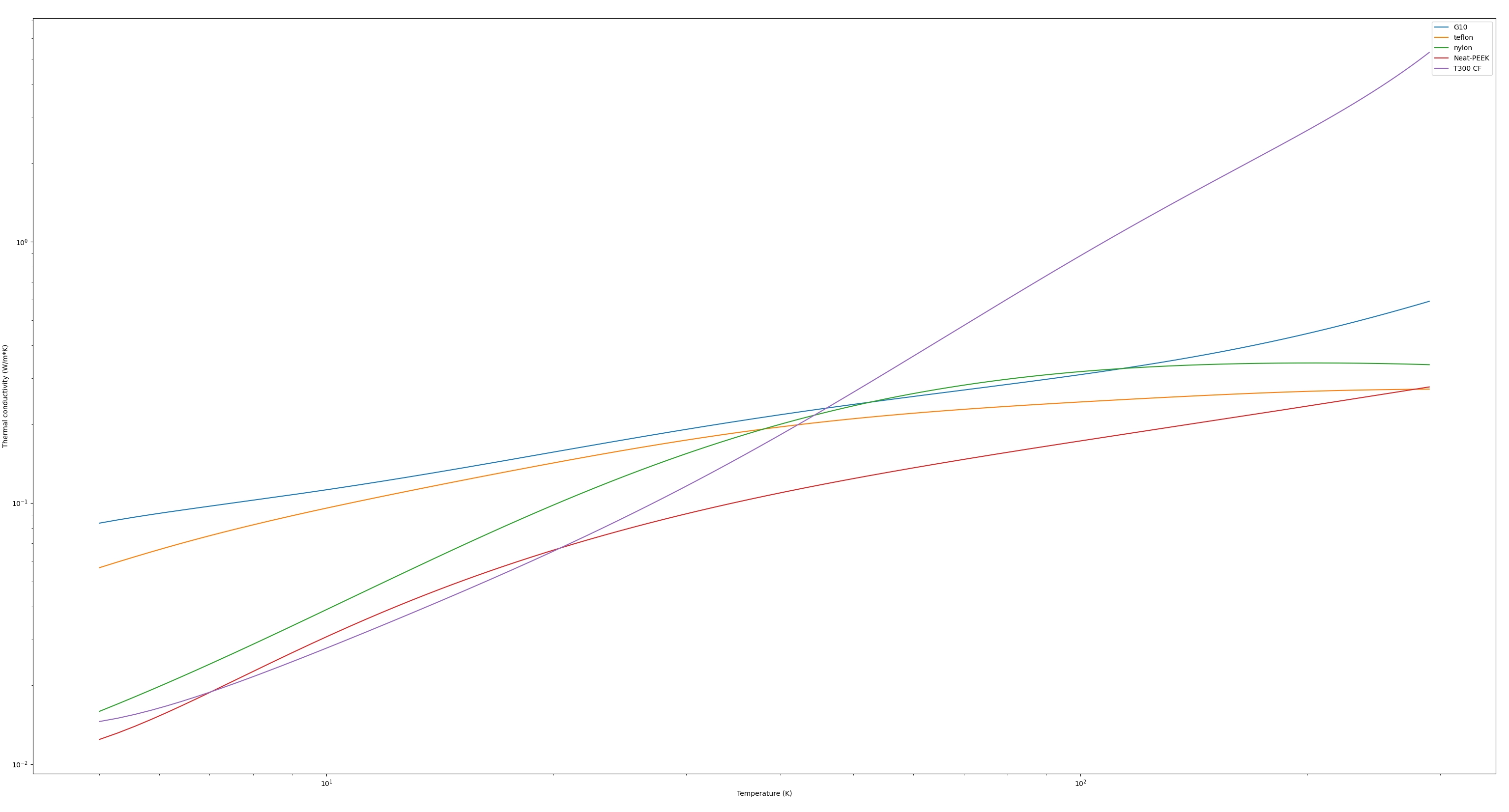
- Thermal conductivity of common materials: cryogenic-thermal-conductivity-of-common-materials.webp
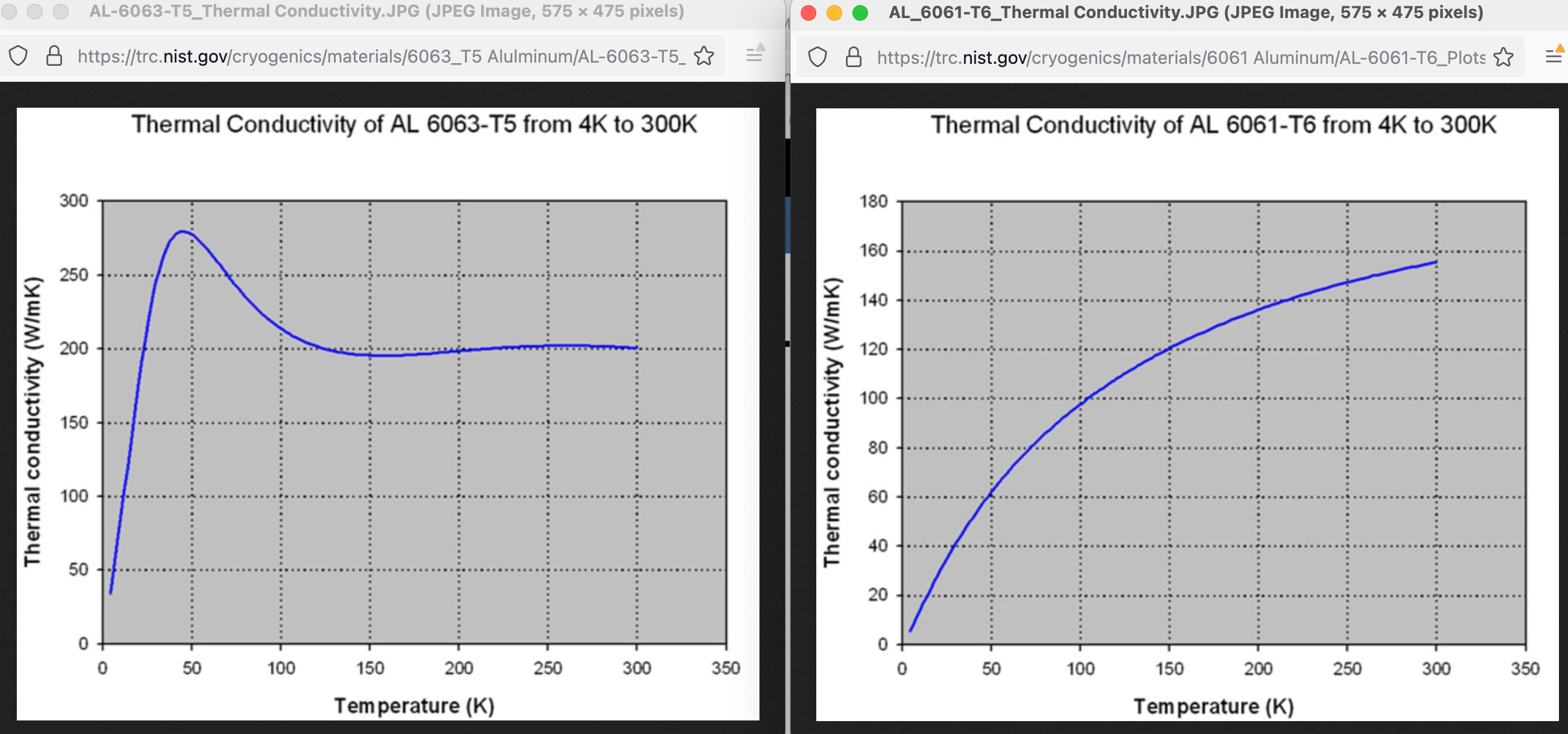
Choice of aluminum alloy
- 6063 aluminum has a much higher thermal conductivity at low temperatures than 6061 and is about the same price
- Comparison here: Design notes-20240614162008813.webp
- Comparison from the NIST cryogenic thermal properties site
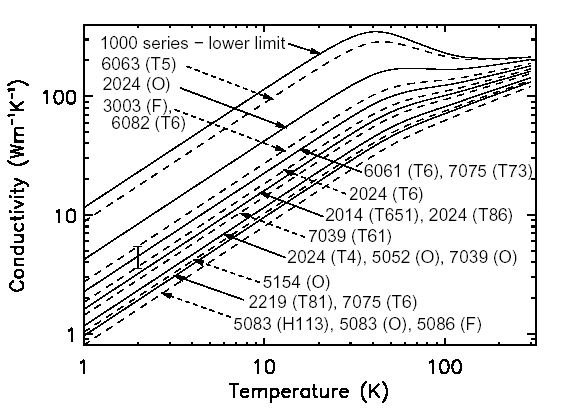
https://reference.lowtemp.org/alkappa.html
Plating / finish of machined parts
- Ideally we want to plate the aluminum pieces that get cold with some kind of shiny coating (e.g. electroless nickel)for the following reasons:
- It lowers the emissitivity of the surface significantly, reducing blackbody heating. Oxidized aluminum has an emissivity of ~0.3, while polished metals have emissivities on the order of ~0.03
- The plating prevents the surface from oxidizing, making electrical connections to ground much easier
- It looks nice
- Unfortunately, this is only easy for CNC machined parts — the lasercut services don’t typically offer plating service that results in a high polish
Thermal contact
- It’s critical to use grease on all metal-metal thermal contacts. See Ekin section 2.6 for further discussion, but the basics are as follows:
- Without grease, thermal conductivity depends highly on the force applied to the metal-metal joint and is usually much lower than grease unless an incredible amount of force is used
- With grease, thermal conductivity only depends on the total area of metal-metal contact
- At 4K, a 10 cm^2 area of greased metal-to-metal contact yields a thermal boundary conductance of 1.15 K/W, meaning for every ~1mW of heat load, the temperature will raise ~1.15 mK
- At 40K, that same 10 cm^2 area produces a thermal boundary resistance of 0.15 K/W
Clearance hole chart
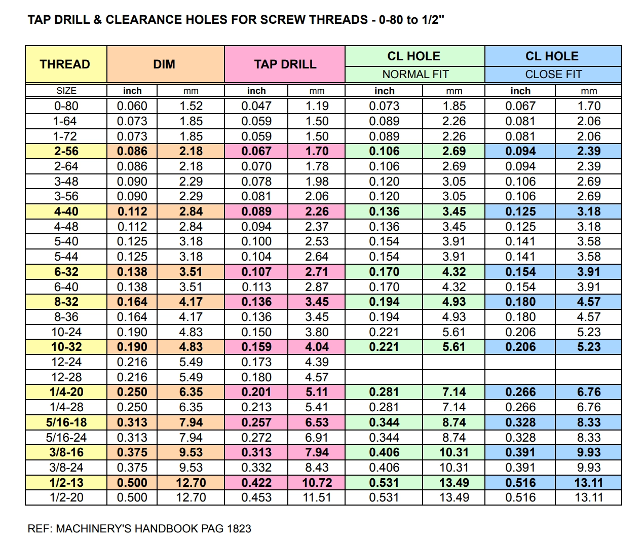
https://www.design1st.com/Design-Resource-Library/engineering_data/TapDrillClearanceHoles.pdf
Misc
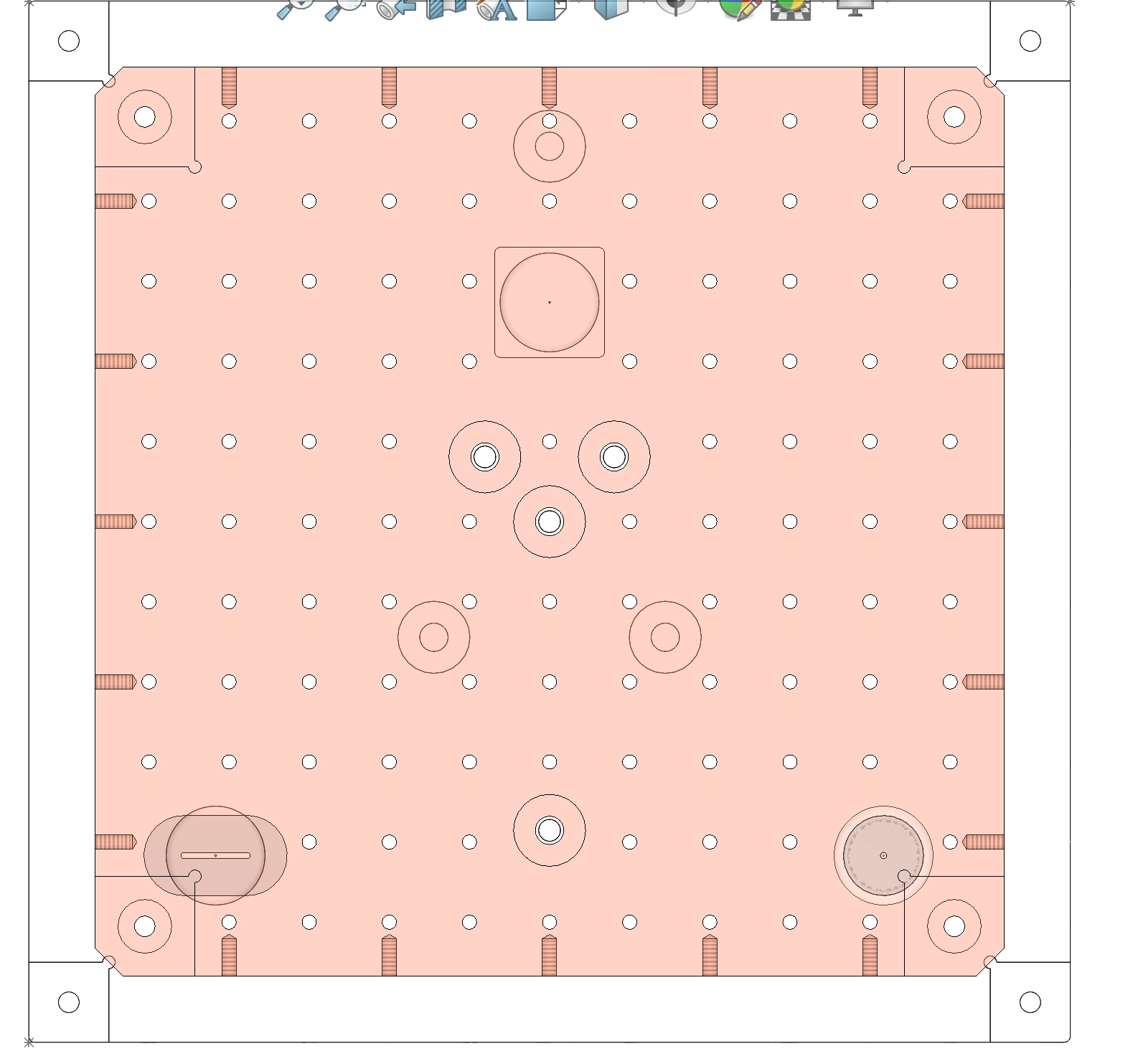
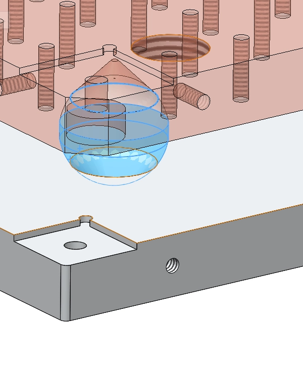
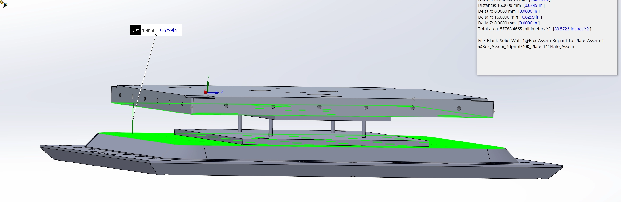
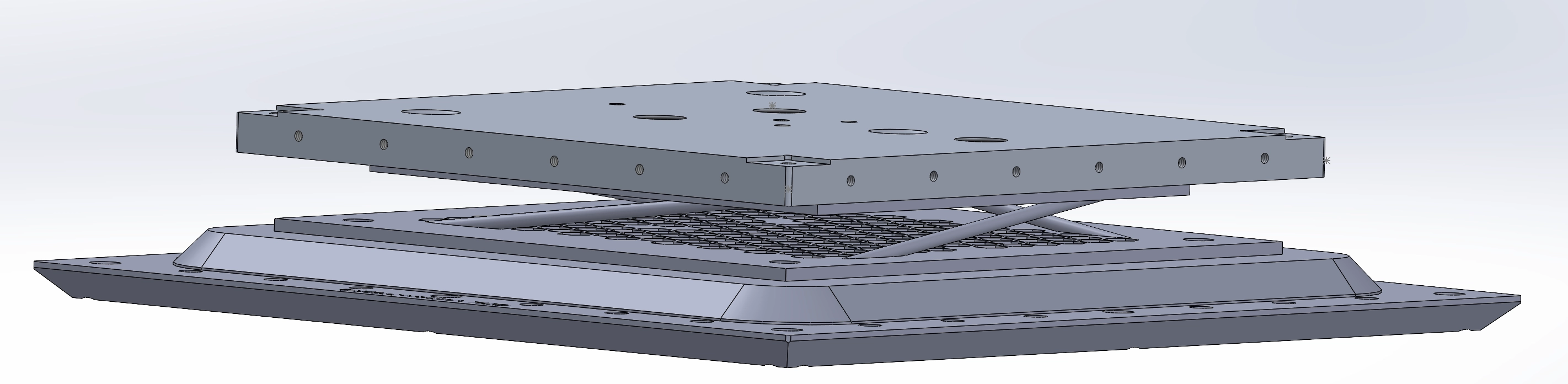
Replacing PEEK balls with 3D printed structure 10/7/24
WHAT: We believe our initial design the the PEEK balls may be limiting our lower base temperature.
WHY: When designing for the PEEK balls, we did not expect deformity and thought that the spheres would have minimal contact area with the plates. Our cooldowns have not reached below 3K unless we use no PEEK screws holding the plates together. This leads us to believe that the PEEK screws + PEEK balls together don’t have enough thermal resistance and the balls by themselves likely have too much power transmission with just themselves.
HOW: 3D print ABS platform with small pegs that theoretically have more thermal resistance than PEEK balls + PEEK screw.
Reference Pictures:

Estimating Power transmission through PEEK ball
Assumed dimensions:
- Diameter: 12e-3 m
- Length between surfaces 10e-3 m
- Area = = 0.113e-3 m
300K to 40K
Single PEEK Ball
- Power transmission = 623.875 mW
- Thermal conductance = 0.00240 W/K
- Thermal resistance = 416.750 K/W
Three PEEK balls - Total Power transmission for 3 balls = 1869 mW
60K to 2.89K (Best cooldown shows 60K on bottom 40K and 2.89K on 4K plate with no peek screw)
Single PEEK Ball
- Power transmission = 55.253 mW
- Thermal conductance = 0.000967 W/K
- Thermal resistance = 1033.594 K/W
Three PEEK balls - Total Power transmission for 3 balls = 165 mW
3D print Power transmission
Assumed dimensions:
- Diameter: 3e-3 m
- Length between surfaces 7e-3 m
- Area = = 7.069e-6 m
NOTE: We assume a G10 thermal conductivity integral since we don’t have a fit for ABS. ABS looks to be similar to G10/Teflon/Nylon.
Source: https://iopscience.iop.org/article/10.1088/1757-899X/102/1/012022
300K to 40K
Single ABS Peg
- Power transmission = 107.056 mW
- Thermal conductance = 0.000412 W/K
- Thermal resistance = 2428.627 K/W
Three ABS Pegs - Total Power transmission for 4 ABS pegs = 428 mW ( 4.36 X difference and or 77% percent difference in power transmitted compared to PEEK above)
60K to 2.89K (Best cooldown shows 60K on bottom 40K and 2.89K on 4K plate with no peek screw)
Single ABS Peg
- Power transmission = 10.643 mW
- Thermal conductance =0.000186 W/K
- Thermal resistance = 5366.076 K/W
Three ABS Pegs - Total Power transmission for 4 ABS pegs = 42.572 mW ( 3.875 X difference and or 74% percent difference in power transmitted compared to PEEK above)
First CAD Model
- Rod diameter: 2
- Rod length: 10mm
- Rod Quantity: 4
- Rod Material: PLA
- Estimating using G10
300K to 40K
Single PLA Peg
- Power transmission = 33.306 mW
- Thermal conductance =00.000128 W/K
- Thermal resistance = 7806.301 K/W
Four PLA Pegs - Total Power transmission for 4 PLA pegs = 133.224 mW
Second CAD Model
- Rod diameter: 3
- Rod length: 51mm
- Rod Quantity: 4
- Rod Material: PLA
- Estimating using G10
300K to 40K
Single PLA Peg
- Power transmission = 14.69mW
- Thermal conductance = 5.652e-05 W/K
- Thermal resistance = 17694 K/W
Four PLA Pegs - Total Power transmission for 4 PLA pegs = 58.76 mW
The problem with the above design is that it can not take a large vertical force, in which the 4 pillars begin to touch the bottom plate causing a short.
Replacing 4K nylon balls with 3D print
Assumed dimensions:
- Diameter: 12e-3 m
- Length between surfaces 10e-3 m
- Area = = 0.113e-3 m
60K to 2.89K (Best cooldown shows 60K on bottom 40K and 2.89K on 4K plate with no peek screw)
Single Nylon Ball
- Power transmission = 96.878 mW
- Thermal conductance = 0.001696 W/K
- Thermal resistance = 589.504 K/W
Three Nylon balls - Total Power transmission for 3 balls = 290.634 mW
3d print dimensions:
- Diameter: 2e-3 m
- Length between surfaces 5e-3 m
- Area = = 0.113e-3 m
60K to 2.89K (Best cooldown shows 60K on bottom 40K and 2.89K on 4K plate with no peek screw)
Single PLA Peg
- Power transmission = 6.622 mW
- Thermal conductance =0.000116 W/K
- Thermal resistance = 589.504 K/W
Four PLA Pegs - Total Power transmission for 3 balls = 26.488 mW
~ 11 X Less power transmission with 4K print
Probe Station Arm 3D print
Goal: Replace 2 x SendcutSend Al blocks and 1x G10 rod with 3d print.
G10 Rod dimensions:
- Diameter = 9.525 mm
- Wall Thickness = 1.5878 mm
- Length = ~ 20.6mm
- Material: G10
Thermal properties of G10 Rod with dimensions above from 300K to 90K: - Power transmission = 184.25 mW
- Thermal conductance = 0.00084 W/K
- Thermal resistance = 1194.040 K/W
Using flat prints with PEEK tubes
300K to 40K
PLA
Assumed dimensions:
- Diameter: 3e-3 m
- Length between surfaces 10e-3 m
- Area = = 7.069e-6 m
Single PLA Peg
- Power transmission = 74.93mW
- Thermal conductance = 0.000288 W/K
- Thermal resistance = 3469.467 K/W
Four PLA Pegs
- Total Power transmission for 4 PLA pegs = 300 mW
PEEK
Assumed dimensions:
- Diameter: 9.525e-3 m
- Wall thickness = 1.6e-3 m
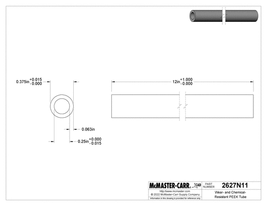
Single PEEK Peg
- Length between surfaces 10e-3 m
- Power transmission = 219 mW
- Thermal conductance = 0.0008475 W/K
- Thermal resistance = 1183 K/W
Assumed dimensions:
- Diameter: 6.35e-3 m
Single PEEK Peg
- Length between surfaces 10e-3 m
- Power transmission = 174 mW
- Thermal conductance = 0.0006719 W/K
- Thermal resistance = 1488 K/W
Choosing rod insert for 300K to 40K stage for 3D prints
Rod vs Tube observations: Rods are found in smaller diameters than tubes. Despite a small tube wall thickness, their diameter is almost or more than double the diameter of the smallest rod diameter. This leads to a larger surface area in which for heat to pass through. This is not ideal. If the tube can be found that’s near the rod diameter, the tube would have less surface area.
Assumed dimensions:
- Length = 10mm
- Single Peg
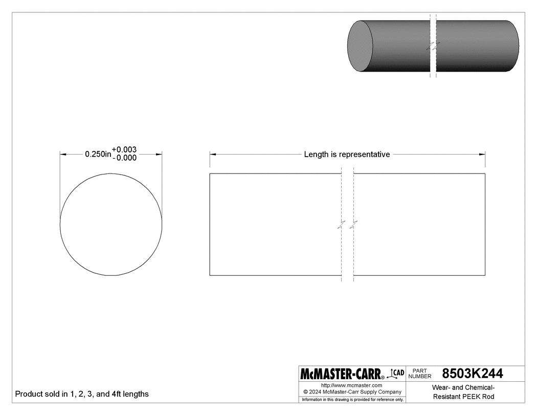
PEEK
- Diameter 6.35 mm
- McMaster #: 8503k244
- Power transmission: 175 mW
Carbon Fiber
- Diameter: 3.175mm
- McMaster #: 2153t15
- Power transmission: 477 mW
- Diameter: 2.38125 mm (3/32)
- McMaster #: 2153t13
- Power transmission: 268 mW
- Diameter: 2.9972 mm (3/32)
- Tube thickness: 0.5mm
- McMaster #: 2153t113
- Power transmission: 236 mW
Nylon
- Diameter: 3.175 mm
- McMaster #: 8541k12
- Power transmission: 66 mW
Conclusion: Given the available sizes on McMaster, Nylon rods provide a large diameter and low heat load transferred to the 40K stage. The factors that must be considered are the 300K to 40K temperature range in terms of thermal conductivity and the sizes available for PEEK, Nylon, and Carbon fiber.
Choosing rod insert for 50K to 5K stage for 3D prints
Assumed dimensions:
- Length = 10mm
- Single Peg
PEEK
- Diameter 6.35 mm
- McMaster #: 8503k244
- Power transmission: 11.27 mW
Carbon Fiber
- Diameter: 3.175mm
- McMaster #: 2153t15
- Power transmission: 4.08 mW
- Diameter: 2.38125 mm (3/32)
- McMaster #: 2153t13
- Power transmission: 2.3 mW
- Diameter: 2.9972 mm (3/32)
- Tube thickness: 0.5mm
- McMaster #: 2153t113
- Power transmission: 2.02 mW
Nylon
- Diameter: 3.175 mm
- McMaster #: 8541k12
- Power transmission: 4.78 mW
Conclusion: If my thermal conductivity fit is generally correct (ignoring pattern hatching / direction which is quite important for carbon fiber), the carbon fiber tubes will preform better thermally than nylon. I will get both and test.